


Harmonic drive, mechanical speed-changing device, that reduces the gear ratio of a rotary machine to increase torque. It operates on a principle different from that of conventional speed changers. The device consists of a thin ring that deflects elastically as it rolls inside a slightly larger rigid circular ring. There are three elements in a basic harmonic drive: A circular spline, a flexspline, and a wave generator. The circular spline has internal teeth that mesh with external teeth on the flexspline. The flexspline has fewer teeth and consequently a smaller effective diameter than the circular spline. The wave generator is elliptical in shape and acts as a link with two rollers that rotates within the flexspline, causing it to mesh with the circular spline progressively at diametrically opposite points. If the wave generator (the input) rotates clockwise while the circular spline is fixed, the flexspline (the output) will rotate or roll inside the circular spline at a much slower rate in a counterclockwise direction.
-
![LCD Harmonic Reducer]() LCD Harmonic Reducer
LCD Harmonic ReducerThe flexspline of the LCD strain wave
-
![LCS Harmonic Reducer]() LCS Harmonic Reducer
LCS Harmonic ReducerStandard cup-shaped flexspline strain
-
![LCSG Strain Wave Gears]() LCSG Strain Wave Gears
LCSG Strain Wave GearsThe LCSG high-torque cup-shaped
-
![LHD Harmonic Reducer]() LHD Harmonic Reducer
LHD Harmonic ReducerThe flexspline of the LHD ultra-flat
-
![LHS Strain Wave Gears]() LHS Strain Wave Gears
LHS Strain Wave GearsLHS harmonic drive reducer has a hollow
-
![LHSG Harmonic Reducer]() LHSG Harmonic Reducer
LHSG Harmonic ReducerThe LHSG high-torque hollow-shaft
-
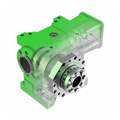
![4th Axis NC Rotary Table]() 4th Axis NC Rotary Table
4th Axis NC Rotary TableThe 4th axis NC Rotary Table from
-
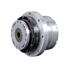
![KMF Torque Motor]() KMF Torque Motor
KMF Torque MotorKMF high-torque frameless direct drive
-
![LSS Harmonic Reducer]() LSS Harmonic Reducer
LSS Harmonic ReducerLSS Harmonic Reducer adopts our newest
-
![LHT Harmonic Reducer]() LHT Harmonic Reducer
LHT Harmonic ReducerLHT Harmonic Reducer features a hollow


